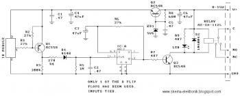
Use this Infrared toggle switch for wireless switching. You need to add IR receiver to electronic device for switching using this circuit.
COMPONENTS
R8________________ 680R
R7, R9____________ 4K7
R1, R2, R4, R6____ 27K
R3________________ 100K
R5________________ 1M
C1, C2, C5________ 470nF
C3, C4, C6________ 47u/16v ecap
IC________________ 4013
Q2, Q3____________ BC548
Q1________________ BC558
D1________________ 1N4148
D2________________ 1N4004
ZD1_______________ Zener diode 5V6
IR receiver module
LED
Miniature relay AZ-SH-112L
All modern IR remote control devices produce a continuous coded stream of pulses at 37.9 kHz when any button on the module is pressed. These IR pulses are detected and decoded by a receiver (your TV, VCR etc.) and the appropriate function activated. In our Kit the coded stream is converted into a single pulse and that single pulse is used to toggle a relay on & off. The coded information is lost. Only the fact that a button was pressed on your remote control unit is detected.
More about this Infrared Toggle Switch, download the manual
