Digital Volume Controller

Tags
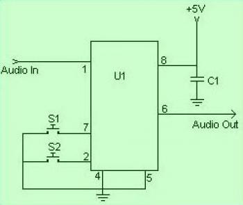
If you need digital volume control, then this circuit will great for you. Just press the button and you will be able to increase and decrease the volume level. This circuit is for 1 kanal only. For stereo audio, you need to build 2 similiar circuit and use push button switch which have double input and double output.
Digital Volume Controller  circuit diagram

Digital Volume Controller  circuit diagram

22 Watt Stereo Audio Amplifier

Tags
With one single IC, you can build stereo audio amplifier. The circuit is simple, easy made and low in cost. Please take a note that you need headsink on the IC to prevent overheat.
electronic circuit diagram

Component List:


R1
C1,C2
C3
C4
C5
C6
U1
MISC
39K 1/4 Watt Resistor
10uf 25V Electrolytic Capacitor
100uf 25V Electrolytic Capacitor
47uf 25V Electrolytic Capacitor
0.1uf 25V Ceramic Capacitor
2200uf 25V Electrolytic Capacitor
TDA1554 Two Channel Audio Amp Chip
Heatsink For U1, Binding Posts (For Output), RCA Jacks (For Input)

10 LED Sound Level Meter

Tags
This is sound level meter for your hand made audio device. This circuit will display like spectrum in Jet Audio software.
10 LED Sound Level Meter circuit diagram

Supply voltage can be from 3V to 20V. The input is set for audio line voltage (1V peak to peak) and has a max input voltage of 1.3V. To make the circuit use a moving dot display instead of bar graph display, Pin 9 can be should be disconnected from +V.

Parts List.


C1
C2, C3
R1, R3
R2
R4
R5
D1
Q1
LED1-LED10
U1
MISC
2.2uF 25V Electrolytic Capacitor
0.1uF Ceramic Disc Capacitor
1K 1/4W Resistor
10K 1/4W Resistor
100K 1/4W Resistor
1M 1/4W Resistor
1N4001 Silicon Diode
BC 558 PNP Transistor
Standard LED or LED Array
LM3915 Audio Level IC
Board, Wire, Socket For U1

8 Watt Audio Amplifier

Tags
This is mono audio amplifier. If you need stereo amplifier, then build 2 similiar circuits. Don't forget to add heatsink on the IC.
8 Watt Audio Amplifier circuit diagram

Component List:
C1 - 10uf Electrolytic Capacitor
C2 - 470uf Electrolytic Capacitor
C3 - 0.1uF Disc Capacitor
C4 - 2000uf Electrolytic Capacitor 2200uF
R1 - 2.2 Ohm Resistance (Anything Within 10% tolerance)
R3 - 220 Ohm Resistance (Anything Within 10% tolerance)
IC1 - LM383 IC

18 watt Audio Amplifier using MOSFET

Tags
18 watt Audio Amplifier using MOSFET circuit diagram

Components list:

R1………………2K2 1/4W Resistance
R2………………27K 1/4W Resistance
R3R4………….2K2 1/2W Trimmers
R5………………100R 1/4W Resistance
R6………………1K 1/4W Resistance
R7,R8……….. .330R 1/4W Resistance

C1 ………………22µF 25V Electrolytic Capacitance
C2 ………………47pF 63V Polyester or Ceramic Capacitance
C3,C4 …………100µF 50V Electrolytic Capacitance
C5 ………………2200µF 50V Electrolytic Capacitance

Q1 ………………BC550C
Q2 ………………IRF530 or MTP12N10
Q3……………… IRF9530 or MTP12P10

19 Watt Audio Amplifier

Tags
19 watt audio amplifier based on single IC LA4440. I've built this circuit once and give me great audio quality for my hand made audio. Very easy and cheap for beginner.

Here the schematic and specification:
electronic circuit diagram

electronic circuit diagram

Water Level Alarm

Tags
Water Level Alarm circuit diagram
More explanation about water level circuit, please go to this page.

Description:
This circuit will trigger with any fluid with a resistance under 900K between the maximum separation distance of the probes. Let me explain further. The circuit uses a 4050B CMOS hex buffer working on a 5 volt supply.

Headphone Stereo Amplifier

Tags
Headphone Stereo Amplifier circuit diagram
Above image is the schematic diagram of headphone stereo audio amplifier. The left and right channel have identical schematic. Use the potensiometer to balancing the volume level between right channel and left channel.

Water Activated Alarm

Tags
Water Activated Alarm circuit diagram
This simple circuit uses timer IC to generate frequency. Emitter current from transistor BC 109C powered the IC to work, so the transistor work similiar as switch work. Under dry conditions, the transistor will have no bias current and be fully off. As the probes get wet, a small current flows between base and emitter and the transistor switches on. A larger current flows in the collector circuit enabling the 555 osillator to sound.

An On/Off switch is provided and remember to use a non-reactive metal for the probe contacts. Gold or silver plated contacts from an old relay may be used, however a cheap alternative is to wire alternate copper strips from a piece of veroboard. These will eventually oxidize over but as very little current is flowing in the base circuit, the higher impedance caused by oxidization is not important. No base resistor is necessary as the transistor is in emitter follower, current limit being the impedance at the emitter (the oscillator circuit).

Infrared Switch

Infrared Switch circuit diagram
Infrared Switch circuit for common use, please visit this page for complete explanation.

This is a single channel (on / off) universal switch that may be used with any Infra Red remote control using 36-38kHz. (This is a very common remote handset frequency). In place of IR1 a TSOP1738 receiver may be used.

Any "button" of any remote control may be used to work this universal switch. The button must be pressed for about one and a half seconds (determined by R3 and C2) before the relay will operate. The circuit will remain in this state (latched) until reset. To reset, any button is pressed on the remote handset and held for a short duration.

For example, if you were watching TV, you could press and hold any button on the TV remote to trigger the circuit. In order not to change channel, you could press the button of the channel you are watching. You can connect anything to the relay, for example a lamp, but make sure that the relay contacts can handle the rated voltage and current.

Sound Effects Alarm Generator

electronic circuit diagram

This schematic in very simple and easy to made. The IC produces all the sound effects, the output at Pin 3 being amplified by the transistor. A 64 ohm loudspeaker can be substituted in place of the 56 ohm resistor and 8 ohm loudspeaker. The 2 pole 4 way switch controls the sound effects. Position 1 (as drawn) being a Police siren, position 2 is a fire engine sound, 3 is an ambulance and position 4 is a machine gun effect. The IC is manufactured by UMC and was available from Maplin electronics code UJ45Y. At the time of writing this has now been discontinued, but they have have limited stocks available.

NiCad Battery Charger

NiCad Battery Charger circuit diagram

This simple and low cost battery charger uses a single transistor as a constant current source. The voltage across the pair of 1N4148 diodes biases the base of the BD140 medium power transistor. The base-emitter voltage of the transistor and the forward voltage drop across the diodes are relatively stable. The charging current is approximately 15mA or 45mA with the switch closed. This suits most 1.5V and 9V rechargeable batteries.

The transformer should have a secondary rating of 12V ac at 0.5amp

Low Cost Tone Control Circuit

Tags
Low Cost Tone Control circuit diagram

This cheap tone control circuit provides a maximum cut and boost of around 10dB at 10K and 50Hz. Two potensiometer used to control the high frequency (treble) and low frequency (bass).

The first BC109C transistor (left hand side) is acting as a buffer. It provides the circuit with a high input impedance, around 250k has a voltage gain of slightly less than unity. As the Baxendall tone control circuit is a passive design, all audio frequencies are attenuated. The position of the controls and reactance of the capacitors alters the audio response. The last transistor provides a slight boost of about 3x. The output is designed to feed an amplifier with input impedance of 10k to 250k. Both tone controls should be linear type potentiometers.

Tweeter Crossover

Tags
Tweeter Crossover circuit diagram
This is tweeter (high frequency speaker) crossover which will filter the treble (high frequency) to be feed to tweeter. The bass (low frequency) cannot pass the tweeter speaker since there is low pass filter made of C1, C2 and R1 assembled before the tweeter.

Notes

  • The tweeter can be a 2 to 3 inch, 4 to 8 Ohm one .
  • R1 is used to adjust match the the tweeters output level to that of woofer.
  • C1 and C2 are electrolytic capacitors.
  • R1 should be rated more than 2 Watts.

Low Cost Mic Mixer

Tags
Low Cost Mic Mixer circuit diagram

This is the schematics of a simple low cost mic mixer that can be assembled from the components in your junk box. This two channel mike mixer is designed for handling high impedance dynamic microphones. Transistor Q1 can be any general purpose pnp transistor like BC177 or BC558.

How ever better the transistor quality better the performance. Resistors R2 and R3 can be used for the level control of input signals.

Notes

  • All capacitors are of ceramic type.
  • Always use a battery two reduce noise .
  • Avoid using power transistors as Q1. This is because power transistors have high leakage current and it adds to the noise which is not suitable for our purpose here

source: circuitstoday.com

12 Watt Audio Amplifier

Tags
12 Watt Audio Amplifier circuit diagram

This low cost amplifier is simple and give you good result. Here the op-amp used is uA 741 which produces the required gain.The four transistors are wired as complementary Darlington’s which produces the drive for the speaker.

The voltage drop across the resistors R2 and R3, are used as the input of the Darlington pairs . As the input current to the op-amp depends on the level of the signal op amp is amplifying the voltage drop across the resistors R2 and R3 will be proportional to the input signal. These voltage drops are given to the base of Darlington pairs. The amplification is stabilized as a result of the negative feedback from the junction of collectors of Q2 and Q4. The theory may seem little awkward for you. But its working good.cSuch a simple but stable circuit as this can produce a reasonable output of 12W on a 4 Ohm speaker.

2W Mono Audio Amplifier

Tags
2W Mono Audio Amplifier circuit diagram

This circuit diagram is very simple, very easy to build and will be great idea for newbie or student project.

The IC TDA7052 is a mono output amplifier coming in a 8-lead DI package (DIP). The device is mainly designed for battery-operated portable audio circuits. The features of TDA 7052 include ,no external components needed, no switch-on or switch-off click sounds, great overall stability, very low power consumption(quiescent current 4mA), low THD, no heatsinks required and short-circuit proof.

The gain of TDA 7052 is fixed internally at 40 dB. . To compensate the reduction of output power due to low voltage supply the TDA7052 uses the Bridge-Tied-Load principle
(BTL) which can provide an output of around 1 to 2 W Rms(THD = 10%) into an 8 Ohm load with a power supply of 6 V.

In the circuit the potentiometer can be used to control the volume. Capacitor C1 and C2 are meant for filtering the supply voltage if a battery eliminator is used as supply source. For operations using a battery C1 and C2 are no necessary.