Rain Detector Alarm


This is the circuit diagram of rain detector alarm. When the sensor is wetted with the water, then the alarm will be activated. This circuit can be used for other purposes.

A 555 astable multivibrator is used here which gives a tone of about 1kHz upon detecting water. The sensor when wetted by water completes the circuit and makes the 555 oscillate at about 1kHz. The sensor is also shown in the circuit diagram.

Two Tone Electronic Siren Circuit


This is the circuit diagran of two tone electronic siren. The scheme is simple and easy to built, it based on two ICs with different task: produce audio signal and amplify the audio signal.

List of Components:

R1-R2-R3: 2.2KΩ
R4: 1KΩ
R5: 10K (potentiometer)
R6: 470Ω
C1 - C2: 10 uF
C3 - C4: 470 nF
C5: 10 uF
C6: 220 uF
IC1: Integrated Circuit TTL 7400
IC2: LM386
Z1: Zener 5 volts 1/2 watt
Speaker 8 Ω

PWM Controller Circuit using SN75603 and SN75604


Here the circuit diagram of PWM Controller which uses complementary half-H peripheral drivers SN75603 and SN75604, with totem-pole outputs rated at 40 V and 2.0 A. These drivers effectively place the motor in a full-bridge configuration, which has the ability to provide bidirectional control.

USB Cellphone Charger


This is the schematic diagram of cellphone charger circuit which connecter to the USB as main power. Whit this circuit, you can charger your cell phone from USB port in your PC or notebook.

The majority of the cellphones battery is appraised 3.6 volts at 1000 to 1300 mah. These battery packs have 3 Nimh or Lithium cells having 1.2 volt rating. Generally the battery pack requires 4.5 volts and 300-500 mA current for quick charging. Anyway, low present charging is better to build the proficiency of the battery. The circuit depicted here gives 4.7 directed voltage and sufficient present for the moderate charging of the cellphone.

1.3-12V Small Variable Power Supply


This is a small variable power supply delivers adjustable output voltage of 1.3v-12v. The current output determined by R3. With current setting (see part list), it will deliver current output about 1A.

220V Light-Operated On/Off Switch

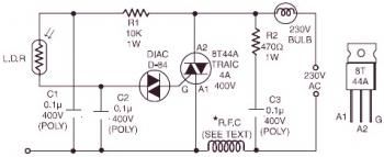
220V Light-Operated On/Off Switch circuit diagram

This schematic diagram is a light-operated, remote-controlled solidstate switch circuit to handle lamp. While in darkness, the resistance of Light Dependent Resistor (LDR) is extremely hight, it shoots up to megohm range. As a result, the triac isn't going to have gate drive and therefore it doesn't conduct.

Gold Detector Schematic

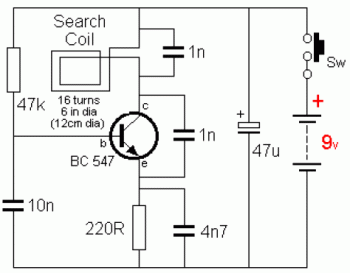
Gold Detector Schematic circuit diagram

Here the very simple and easy build gold detector circuit. The circuit capable to sense gold or metal or coins from a distance of about 20cm, depending on the size of the object to detect.

The circuit oscillates at about 140kHz and a harmonic of this frequency is detected by an AM radio. You can simply tune the radio receiver until a squeal is detected.

Simple Intercom Circuit with Transistors

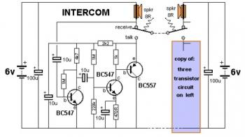
Simple Intercom Circuit with Transistor

This is a 2-station simple intercom circuit build based on transistors part and using common 8R mini speakers. The speaker works as microphone and generate sound, so there is no need microphone for this intercom. The "press-to-talk" switches should have a spring-return so the intercom can never be left ON, push on switch can be used for this kind of task.