12W HiFi Stereo Audio Amplifier

Tags
12W HiFi Stereo Audio Amplifier circuit diagram

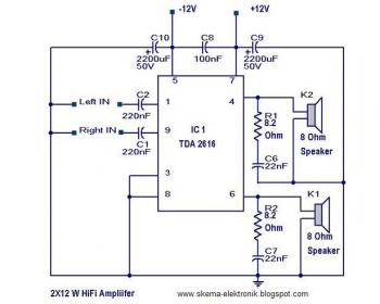
Here is the circuit of a 2X12 watt HiFi stereo audio amplifier circuit using IC TDA 2616 from Phillips. A quiet simple and robust circuit using very less components. This makes the circuit ideal for a portable power amplifier. The circuit delivers 12 W power on 8 Ohm speaker for each channel at +/- 12 V dual supply.

The TDA2616 is a stereo power amplifier IC comes in a 9-lead single-in-line (SIL9) plastic power package (SOT131). This IC is specially designed for mains fed amplifier circuits, such as stereo radio, tape and television . The IC has good gain balance of both channels and Hi-fi in accordance with IEC 268 and DIN 45500 standards. Also the IC TDA 2616 has special inbuilt circuit for the suppression of noise signals at the inputs, during switch-on and switch-off. This prevents click sounds during power on and power off.

Notes.

  • All capacitors except C10 & C9 are ceramic.
  • All capacitors must be rated 50V.
  • Use a well regulated and filtered +/- 12 V dual power supply that is able to provide at least 2 A continuous current.

TDA 2616 Pin assignment & layout.

12W HiFi Stereo Audio Amplifier


source: circuitstoday.com

150W Audio Power Amplifier

Tags
150W Audio Power Amplifier circuit diagram

For an amplifier with 150 Watt in power, may be this is the cheapest one . This amplifier circuit built based on two Darlington power transistors TIP 142 and TIP 147, this circuit can deliver a blasting 150 W Rms to a 4 Ohm speaker.

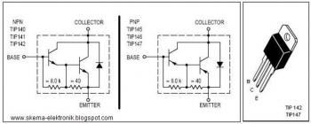
TIP 147 and 142 are complementary Darlington pair transistors which can handle 5 A current and 100V, famous for their ruggedness. Here two BC 558 transistors Q5 and Q6 are wired as pre amplifier and TIP 142, TIP 147 together with TIP42 (Q1,Q2,Q3) for driving the transistors. This circuit is designed so rugged that this can be assembled even on a common board or even by pin to pin soldering. The circuit can be powered from a +/-45V 5A dual power supply. You must try this circuit. Its working great.


150W Audio Power Amplifier

Notes:

  • Remember TIP 142 and 147 are Darlington pairs. They are shown as coventional transistors in figure for ease. So don’t get confused. Even though each of them have 2 transistors, 2 resistors and 1 diode inside, only three pins, base emitter and collector are coming out. Rest are connected internally. So its quite OK to assume each of them as transistor for ease.
  • Use a well regulated and filtered power supply.
  • Connect a 10K POT in series with the input as volume control if you need. Not shown in circuit diagram.

3 Watt Stereo Audio Amplifier

Tags
3W Stereo Audio Amplifier circuit diagram

This very simple circuit is ideal for small power audio applications like portable CD players or radio sets.The circuit is designed strictly as per the datasheet and found to be working great.

The MAX9710 a stereo audio power amplifier IC capable of delivering 3Watts of out put to 4 Ohm loads. MAX9710 can be operated from a single 4.5V to 5.5V power supply , makes it ideal for hand held applications.The IC also features thermal overload protection.

Notes:

  • Use a 5 V DC power supply for powering the circuit.
  • If you want to use a battery ,then use a 6V battery with a IN 4007 diode series to the positive terminal of it.The diode will drop 0.7 V and the IC will get the rated ~5V.This is just a safety recommendation .
  • Assemble the circuit on a good quality PCB or common board.

source: circuitstoday.com

Simple Audio Amplifier

Tags
Simple Audio Amplifier circuit diagram

Here the simple and low cost audio amplifier schematic diagram. The circuit is ideal for a pocket radio or other hand held audio equipments.

The first part of the circuit here is a preamplifier consisting of transistor Q1(2N2222). The collector of the Q3 is coupled to the base of Q2 (2N2905A),which forms a complementary symmetry pair with Q3 (2N3053). The amplified signal is available at the junction of emitter of two transistors.

Notes:

  • For Q1 you can try with any general purpose NPN transistors like BC107, BC148,etc.
  • For Q2 and Q3 you can try any complimentary power transistors. The result may vary slightly. No problem.
  • The can be also powered from a well regulated and filtered 9V DC power supply.
source: circuitstoday.com

50W Audio Amplifier

Tags
50W Audio Amplifier circuit diagram
About the schematic diagram:

The circuit is designed such that most of the components are not critical and can be easily replaced by nearest values.This make it ideal to assemble from your electronics junk box.

The capacitor C1 controls low frequencies and capacitor C2 controls high frequencies.The circuit ia basically a class B amplifier.The transistors 2N 3055 serves the function of driving the speaker.The other transistor functions as pre amplifiers for the driver stage.This is the basic scheme of the circuit.The maximum power level of amplifier can be set by adjusting the 500 Ohm POT connected with the BC107 transistor.

Notes:

  • The circuit can be powered using a 50 V DC power supply with 5A current rating.Up to 60 v can be given to the circuit.Any way the power supply must be well regulated and filters to avoid noise.
  • Adjust the 500 ohm POT to obtain optimum performance.
  • All capacitors must be rated higher than the supply voltage.
  • Volume control can be attained by connecting a 10 K POT in series to the input of the amplifier.(Not shown in circuit).
source: circuitstoday

3 Band Graphic Equalizer schematic diagram

Tags
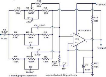
This schematic circuit diagram is very simple. Just need a single op amp IC LF351 (IC1) and few passive components.

3 Band Graphic Equalizer circuit diagram


The component values of this circuit are not very critical and can be replaced with nearest values with a little loss on the performance. This feature make it easy to be assembled from your junk box.

The op-amp LF351 is wired to operate in three frequency ranges- high,medium and low. The circuit is designed such that the circuit produces +/-20 dB boost or attenuation for 50Hz,1KHz and 10Khz by varying POT’s R3, R6 and R9. The maximum amplification for any of these bands at maximum supply voltage is 20dB. The op-amp LF 351 is wired as an inverting amplifier whose response to frequencies 50Hz,1Khz and 10KHz can be varied by adjusting POT’s R3,R6 and R9.

Notes:

  • The circuit can be operated from 6 to 24 V DC .What I recommend is 12V .
  • Use a 12V battery or 12 V DC power supply for the circuit.
  • All capacitors must be rated 15V.
  • A 10uF/15V capacitor must be connected between +ve and -ve pins of LF351 if the power supply is far from the circuit. Not shown in circuit.

Electric Guitar Pre-Amplifier schematic diagram

Tags
Here the schematic diagram of simple pre-amplifier for electric guitar:
Electric Guitar Pre-Amplifier circuit diagram

A pre-amplifier circuit suitable for high impedance type electric guitar pickups is given here.The circuit is based on a uA 741 op-amp (IC1).The IC1 is wired as a non-inverting amplifier.The POT R1 can be used as a volume controller.The POT R6 can be used as tone controller.The switch S1 is used to produce “brilliant” or “soft” tonal effects.

Notes:
  • Assemble the circuit on a good quality PCB or common board.
  • The amplifier can be powered from a 12V battery or 12V DC power supply.
  • Up to 24 V DC can be used to power the circuit. 12 V DC power supply is recommended.
  • The IC 1 should be mounted on an IC base .


Source: circuitstoday.com

Fire alarm circuit

Tags
The works is similiar from previous circuit. the LDR sending the light from lamp. When light from lamp blocked by smoke, the alarm will be activated.

Fire alarm circuit diagram

When there is no smoke the light from the bulb will be directly falling on the LDR. The LDR resistance will be low and so the voltage across it (below .6V). The transistor will be OFF and nothing happens. When there is sufficient smoke to mask the light from falling on LDR, the LDR resistance increases and so do the voltage across it. Now the transistor will switch to ON. This gives power to the IC1 and it outputs 5V. This powers the tone generator IC UM66 (IC2) to play a music. This music will be amplified by IC3 (TDA 2002) to drive the speaker.

The diode D1 and D2 in combination drops 1.4 V to give the rated voltage (3.5V ) to UM66 .UM 66 cannot withstand more than 4V.

Notes.

  • The speaker can be a 8Ω tweeter.
  • POT R4 can be used to adjust the sensitivity of the alarm.
  • POT R3 can be used for varying the volume of the alarm.
  • Any general purpose NPN transistor (like BC548,BC148,2N222) can be used for Q1.
  • The circuit can be powered from a 9V battery or a 9V DC power supply.
  • Instead of bulb you can use a bright LED with a 1K resistor series to it.

Simple fire alarm circuit using IC timer NE555

Tags
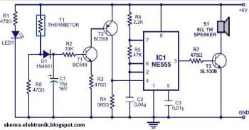
Here the simple file alarm circuit based timer ID NE555. The works is simple, the lamp give light to the LDR (Light Depending Resistor) as light sensor. When the light from the lamp covered with smoke then the LDR will change its resistance value and then activated the alarm.
Simple fire alarm circuit  using IC timer NE555
The thermistor offers a low resistance at high temperature and high resistance at low imperature. This phenomenon is employed here for sensing the fire.

The IC1 (NE555) is configured as a free running oscillator at audio frequency. The transistors T1 and T2 drive IC1. The output(pin 3) of IC1 is couples to base of transistor T3(SL100), which drives the speaker to generate alarm sound. The frequency of NE555 depends on the values of resistances R5 and R6 and capacitance C2.When thermistor becomes hot, it gives a low-resistance path for the positive voltage to the base of transistor T1 through diode D1 and resistance R2.

Capacitor C1 charges up to the positive supply voltage and increases the the time for which the alarm is ON. The larger the value of C1, the larger the positive bias applied to the base of transistor T1 (BC548). As the collector of T1 is coupled to the base of transistor T2, the transistor T2 provides a positive voltage to pin 4 (reset) of IC1 (NE555). Resistor R4 is selected s0 that NE555 keeps inactive in the absence of the positive voltage. Diode D1 stops discharging of capacitor C1 when the thermistor is in connection with the positive supply voltage cools out and provides a high resistance path. It also inhibits the forward biasing of transistor T1.

Power Supply 1.3 - 32 V / 5A with Short Circuit Protection

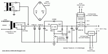
Power Supply 1.3 - 32 V / 5A  with Short Circuit Protection circuit diagram

This is a very easy to build power supply that is based on LM338 5A adjustable voltage regulator. I am using the supply for a long time, have no problem yet. Only current adjust is missing but I overcome this situation by using an LCD panel ampermeter. There is no PCB for the circuit. I took a 3x16 copper plate and strip the unused areas by a knife. If you want you can use analog meters instead of LCD panels.

Notes:

  1. Use thick wires for connections.
  2. When connecting the LM338 to the heatsink use thermal paste.
  3. Use external supplies for LCD panels. They can be 9V batteries. The panels I use draws 1mA current and the batteries last sufficiently long time. If you have small transformers which can supply regulated 9V, you can use them. You need separate transformers for each panel!
  4. The transformer should be 100 Watt but if you don't need high current you can try transformers that you already have. (I can draw 6A from 100Watt transformer.)
  5. If you have multi winding transformer you can use the diode connections shown in schematic. Diodes must be 10-15 A.
  6. Be careful while connecting LM338. Don't put it inverse.
  7. Output of your transformer mustn't exceed 25V AC...


www.circuit-projects.com

Power Supply 1.2 - 12V / 1A with low voltage LED Indicator

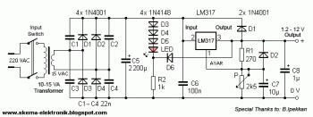
Power Supply 1.2 - 12V / 1A with low voltage LED Indicator circuit diagram

This power supply can provide output voltage 1.2V - 12 with maximal output current is 1A, low voltage LED indicator added in this schematic diagram. The indicator part includes three diodes and one LED. For example you are charging a battery, you can observe the charge status at that moment. Another advantage of this circuit, when the drawn current exceeds 1A (practically 0.85A), the current protector in LM317 intervenes and LED indicator warns you about the very low output voltage.