Positive(+) to Negative(-) Voltage Inverter

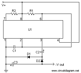
This simpe circuit will convert the positive input voltage become negative voltage.

Schematic diagram:
Positive(+) to Negative(-) Voltage Inverter circuit diagram


Component list:
Part Total Qty. Description
R1 1 24K 1/4 Watt Resistor
R2 1 56K 1/4 Watt Resistor
C1 1 3300pF 25V Ceramic Capacitor
C2 1 47uF 25V Electrolytic Capacitor
C3 1 10uF 25V Electrolytic Capacitor
D1, D2 2 1N4148 Silicon Diode
U1 1 555 Timer
MISC 1 Wire, Board


Notes:
  1. V+ can be anywhere from 4 to 16V. -V is one volt less than V+. So for -12V output, use +13V input. The maximum current output of the circuit is about 280mA, more than enough for a few op amps.
  2. For better regulation, a 79LOxx series regulator can be used.
  3. A zener diode may also be used to regulate the output voltage.
3-30 V/2.5 A Adjustable Stabilized Power Supply

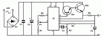
This is Simple 3-30 volt adjustable and stabilized power supply circuit. You can use this circuit for general purpose.

Here the schematic diagram:
3-30 V/2.5 A Adjustable Stabilized Power Supply circuit diagram

Component list:
R1 = 560R 1/4W C1 = 100nF
R2 = 1,2 K 1/4W C2 = 2200uF 35-40V
R3 = 3,9 K 1/4W C3 = 100 pF
R4 = 15K 1/4W C4 = 100uF/ 35V
R5 = 0,15R 5W


D = B40 C3300/2200, 3A rectifier bridge
P1 = 10K potesiometer TR1 = BD 135
IC = LM723 TR2 = 2N3055


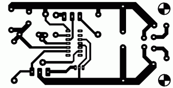
PCB layout:
3-30 V/2.5 A Adjustable Stabilized Power Supply circuit diagram

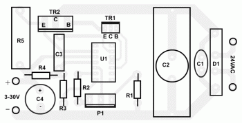
Components placement:
3-30 V/2.5 A Adjustable Stabilized Power Supply circuit diagram

For complete explanation, circuit's works and how to build this circuit into the box, download the full tutorial here

Universal Pre-Amplifier

Tags
Here the universal pre-amplifier schematic diagram for common input device:
Universal Pre-Amplifier circuit diagram


Download the schematic in PDF format

2 Way Cross-Over 3500 Hz (bass and treble)

Tags
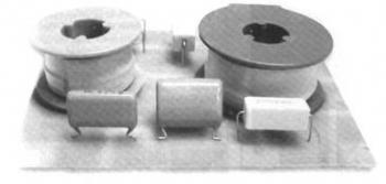
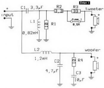
This is 2 way cross-over for your speaker system. This circuit will handle 2 speaker that are woofer (low frequency) an tweeter (high frequency).

The result will shown as below picture:
electronic circuit diagram

Here the schematic diagram of the circuit:
electronic circuit diagram

Visit this page for PCB layout and complete explanation about the circuit.