Running LED

This is the running LED circuit diagram. The LED will "running" (on) one by one. You can use this circuit for many purpose like motorcycle lamp, running character and much more.

Here the schematic diagram with IC timer 555:
Running LED circuit diagram

And use this circuit use NAND logic:
Running LED circuit diagram

Zone Alarm System

electronic circuit diagram


This is the circuit of alarm system with 5 independent zones. Suitable for a small office or 
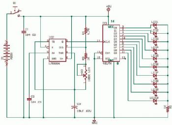
home environment. It uses just 3 CMOS IC's and features a timed entry / exit zone, 4 immediate zones and a panic button. There are indicators for each zone a "system armed" indicator.

Zone 1 is a timed zone which must be used as the entry and exit point of the building. Zones 2 - 5 are immediate zones, which will trigger the alarm with no delay. Some RF immunity is provided for long wiring runs by the input capacitors, C1-C5. C7 and R14 also form a transient suppresser. The key switch acts as the Set/Unset and Reset switch. For good security this should be the metal type with a key.

Circuit works:
At switch on, C6 will charge via R11, this acts as the exit delay and is set to around 30 seconds. This can be altered by varying either C6 or R11. Once the timing period has elapsed, LED6 will light, meaning the system is armed. LED6 may be mounted externally (at the bell box for example) and provides visual indication that the system has set. Once set any contact that opens will trigger the alarm, including Zone 1. To prevent triggering the alarm on entry to the building, the concealed re-entry switch must be operated. This will discharge C6 and start the entry timer. The re-entry switch could be a concealed reed switch, located anywhere in a door frame, but invisible to the eye. The panic switch, when pressed, will trigger the alarm when set. Relay contacts RLA1 provide the latch, RLA2 operate the siren or buzzer.

Simple Electronic Buzzer

Simple Electronic Buzzer circuit diagram

This is a simple electronic buzzer circuit diagram. Cheap and easy to build.
The 555 is used as astable multivibrator operating at about 1kHz and produces a shrill noise when switched on. The frequency can be adjusted by varying the 10K resistor. You may change the 10K resistor with variable resistor.

Variable Power Supply with L200

This is adjustable power supply schematic diagram with IC L200 for its power regulation.

Variable Power Supply with L200 circuit diagram


Voltage output is controlled by 10K variable resistor. Output voltage range value will be about 3 to 15 volts, and current range is about 10mA minimum and 2 amp maximum. Reaching the current limit will reduce the output voltage to zero.

Power Audio Amplifier based on STK400xx

Tags
This is Power Audio Amplifier circuit based on STK400xx series. It's will give you very good quality of sound this circuit is unexpensive too since STK40xx series have low price. It is easy we make a power amplifier using only few external components. The STKxxxx amplifiers, for them we will find in enough eponymous stereo amplifiers , but also in enough activety loudspeakers. They do not need a lot of special knowledge of manufacture, only that attention in pins, in order to they do not break, and one good power supply.

Schematic Diagram:
Power Audio Amplifier based on STK400xx  circuit diagram

Component Part list


R1-4 =1Kohm
R2= 33Kohm
R3-8=100ohm
R5= 0.22ohm 5W
R6=10ohm 2W
R7= 6,8ohm 2W
R9=12Kohm
R10=10Kohm
R11= 680ohm
C1=560 pF 100V ceramic or mylar
C2-7 =1 uF 63V MKT

C3-12 =220 uF 63V
C4-5-10 =100 pF
C6-9 =47uF 63V
C8 =100 nF 100V MKT
C11 =1 nF 100V MKT
C13 =100 uF 25V
C14=10pF 100V ceramic or mylar
L1 =3μH [15 turns of 1mm around R6]
100V ceramic or mylar
F1-2 =2A Fuse fast
IC1=STK4036......STK4044
STK40xx Series:

STK 4036 > Supply: ±35V - ±53,5V; Power (8R load): 50W
STK 4038 > Supply: ±40V - ±58V; Power (8R load): 60W
STK 4040 > Supply: ±43V - ±63V; Power (8R load): 70W
STK 4042 > Supply: ±46V - ±67V; Power (8R load): 80W
STK 4044 > Supply: ±51V - ±74V ; Power (8R load): 100V