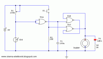
This is a circuit diagram of light detector. This circuit can be used as a sensor of automatic lamp switch, thic circuit also can be used for anti theft alarm circuit.
Schematic diagram:
Use variable resistor R1 to adjust the light threshold at which the circuit triggers. R1's value is chosen to match the photocells resistance at darkness. The circuit uses a CMOS 4001 IC. Gate U1a acts as the trigger, U1b and c form a latch. S1 to reset the circuit. You may used piezo buzzer or LED as output indicator, you may use both of them.
