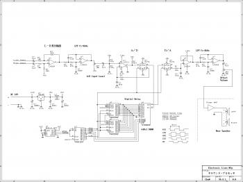
This is the easy build surround sound processor circuit using the digital delay process method. This audio processor isn't applying any unique function ICs that tough to obtain parsonaly, and designed in only common purpose ICs.
The kind of this Surround Processor is producing the surround impact with processing two channels of stereo supply. The majority of those are generates the surround impact with separates reverberations from supply signal and applies any processes, after which mix it to front channels or output as rear channel.
The circuit works and contains three modules:
Separating the Reverberatins
The distinction in between each channels is separated with distinction amplifier from the op-amp. And greater frequencies inside the distinction signal are cut using the LPF.
A-D and D-A conversion
These are composed with common purpose ICs. The A-D converter is basically delta modurator that making use of a comparator plus a D type flip-flop. And it converts analog signal into digital data of one bit, 2 Msa/sec. Following passed digital delay, the bit stream is directly conversion into analog signal using the integrater.
It isn't beneficial that signal to noise ratio and distortion as this A-D, D-A converter.
Digital Delay
For the digital delay method, a DRAM chip is utilised as a FIFO memory. This circuit design demands a 64K bit DRAM, but I utilized a 256K bit DRAM discovered within the junk box. Shift register generates Read-Modify-Write cycle, read out old data and save new data in a single cycle.
And lower byte in the address counter is assined as row address with the DRAM to increment row address every single cycle, to ensure that refresh cycle is often omitted. The FIFO length is 65536 bits and 2 Msa/sec makes 33 msec of delay time.
Surround sound processor circuit source page: http://elm-chan.org/works/srp/report_e.html
