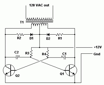
This Inverter takes 12 volt d.c and steps it up to 120 volt a.c. The wattage depends on which transistors you use for Q1 and Q2, as well as the "Amp Rating" of the transformer you use for T1. This inverter can be constructed to supply anywhere from 1 to 1000 (1 KW) watts. If Q1, Q2 are 2N3055 NPN Transistors and T1 is a 15 A transformer, then the inverter will supply about 300 watts. Larger transformers and more powerful transistors can be substituted for T1, Q1 and Q2 for more power.
Parts
C1, C2 >> 68 uf, 25 V Tantalum Capacitor
R1, R2 >> 10 Ohm, 5 Watt Resistor
R3, R4 >> 180 Ohm, 1 Watt Resistor
D1, D2 >> HEP 154 Silicon Diode
Q1, Q2 >> 2N3055 NPN Transistor (see "Notes")
T1 >> 24V, Center Tapped Transformer
Misc:
Wire, Case, Receptacle (for output)
Fuses, Heatsinks, etc.
Note: Don't try to run inductive loads (motors...) off this inverter.

4 comments
Whats the output frequency?? is high frequency like 20KHZ???
some of the component for the 12v to 120v are not found here in nigeria so i used substituts like IN4007 for hep154, but the output is less tha n 50vac i don't understand where i'm wron. as i'm writting, this is the 3rd time i'm designing this inverter but still not working. pliz i need help...
hey , just wondering , i now started in this electronics stuff, y cant i run inductive loads off of this inverter?
Speaking for myself seeing as how i haven't run this circuit except for in my mind, i can see it picking up a resonance and beginning to ring, and overpower the circuit. Needs some type of neutral but it.s gotta be shielded and grounded. Just saying conceptually; i may be wrong. If so point out where so i can learn. Thanks
Jeff