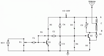
This is the the schematic diagram of 15 watt FM transmiter. The range should be 1-2Km with normal FM receiver.
Components List:
| R1 | 220K |
| R2 | 4.7K |
| R3,R4 | 10K |
| R5 | 100ohm |
| C1,C2 | 4.7uF electrolytic |
| C3,C4 | 1nF |
| C5 | 2-15pF |
| C6 | 3.3pF |
| Q1 | BC547C |
| Q2 | 2N2219A |
| P1 | 25K |
| MIC | ecm series |

3 comments
Hi, just wondering what the specs on the coils are? just wanna find out how exactly yours were made so i get it right.
Cheers.
Hi I also wonder how many turns for the inductor on both sides of the antenna and polarities of the electrolytic capacitors as well. Please email me your answer to chopsticks_71@hotmail.com thank you
HELLO FRIENDS,
I MAID THIS PROJECT SUCCESSFULLY. WITH PROPER FREQUENCY AND STRENGTH.IF YOU WANT HELP THEN CONTACT ME ON kpkpkalpesh@gmail.com or at 08866792042…… i will surly help you to bring out you from the problem :)