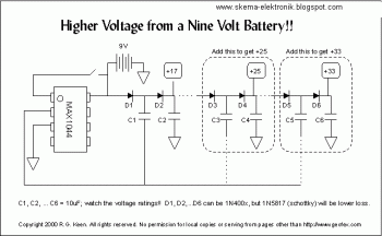
MAX1044 is a charge pump converter - it uses a capacitor as a "bucket" to pump charge from one place to another. Normally, there is a capacitor connected from pin 2 of the 1044 to pin 4. This capacitor is charged between +9V and ground, and then switched in parallel with a capacitor from pin 5 to ground in a way that makes a negative voltage on the second cap.
In this UPverting use, the 1044 still switches pin 2 between +9V and ground just as it would for a voltage inverter. However, we ignore the pin 4 and 5 connections that would make an inverter from it. Instead, we connect two capacitors and diodes as shown (D1, 2, and C1, 2). The voltage on pin 2 of the 1044 is switched from +9V to ground. When it switches to ground, C1 fills with voltage through D1. When it then switches to +9, it pulls the negative terminal of C1 up to +9V. D1 now blocks any flow of current back into the battery, so the charge in C1 flows through D2 into C2. So at C2, we now get almost 18V!
There's more. If we add another two diodes and capacitors (D3, D4 and C3, C4), we can add another 9V to it, as C3 charges to +18 through D3 when pin 2 is at ground, and is pulled up to +25 (+27 minus the voltage drops of the diodes) when pin 2 goes high. We can do it again with D5, D6 and C5, C6 to get +33V. The limit on all this is the losses in the diode voltages. Each time we add a section, we add two more diode drops that we can't take advantage of to charge capacitors. But +33 is not bad for a single 9V battery!
If you build this, you MUST take notice of the voltages on the capacitors. The caps can all be the same value, but C1, C2 need to be 25V units, C3, 4, 5, and 6 can be 35V units, and C5 and C6 might need to be 50V unit just for some safety margin. 1N400x diodes work and are cheap, but the losses are higher than they really need to be. For higher performance and lower losses, it's better to use something like the 1N5817 schottky diodes for low losses. But both will work.
This charge pumping is a very efficient way to convert voltages. The only power lost is that power dissipated in the resistances of the switches inside the 1044 and the series resistance of the capacitors and diodes, as well as the power to run the internal oscillator that flips the switches when needed.
All by itself, the 1044 runs at about 7-10kHz, so there will be ripple of that amount on the C2 output and on the +9V output from the battery as well. Audio equipment that uses this voltage could have a "whine" audible if you're not careful. However, the 1044 has a frequency boost feature. If you connect pin 1 to the power supply (shown by the little open switch) then the oscillator frequency goes up by about 6:1. The oscillator then works well above the audio region. Any whine is then going to be inaudible.

1 comments so far
People should read this.