6V Gel Cell Charger Circuit

6V Gel Cell Charger Circuit diagram


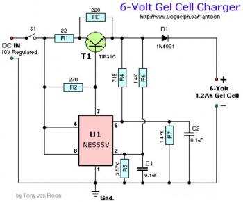
This is the diagram of 6V Gel Cell charger. The circuit is using NE555 timer as oscillator and TPI31T switching transistor. The schematic diagram designed by Tony Van Roon.

Parts List:
R1 = 22 ohm, 1W
R2 = 270 ohm
R3 = 220 ohm
*R4 = 715 ohm, 1%
*R5 = 3.57K, 1%
*R6 = 1.40K, 1%
*R7 = 1.47K, 1%
C1 = 100nF
C2 = 100nF
D1 = 1N4001
T1 = TIP31A, B, C (or equivalent)
U1 = Timer IC NE555V (or equivalent)
S1 = Toggle switch, ON-OFF
* Resistors type are carbon, 1/4 watt, 5% tolerance, unless otherwise indicated.

6V Gel Cell Charger circuit source page
6-8A / 0-28V Variable Power Supply Circuit

6-8A / 0-28V Variable Power Supply Circuit

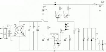
This is the schematic diagram of variable power supply. The output voltage of this power supply circuit can be adjust from 0V to 28V DC, while the current output is static the rang is about 6A up to 8A.

Parts List:
R1 = 2K2 Ohm 2,5 Watt
R2 = 240 Ohm
R3,R4 = 0.1 Ohm 10 Watt
R7 = 6K8 Ohm
R8 = 10K Ohm
R9 = 47 Ohm 0.5 Watt
R10 = 8K2 Ohm
C1, C7, C9 = 47nF
C2 = 4700uF/50v – 6800uF/50v
C3, C5 = 10uF/50v
C4, C6 = 100nF
C8 = 330uF/50v
C10 = 1uF/16v
C11 = 22nF
D1…D4 = four MR750 diodes (MR750 = 6 Ampere diode) or 2 x 4 1N5401 diodes.
D5 = 1N4148, 1N4448, 1N4151
D6 = 1N4001
D10 = 1N5401
D11 = LED
D7, D8, D9 = 1N4001
TR = 2 x 15 volt (30volt total) 6+- Ampere
IC1 = LM317
T1, T2 = 2N3055
P1 = 5k
P2 = 47 Ohm or 220 Ohm 1 Watt
P3 = 10k trimmer pot
F1 = 1 Amp
F2 = 10 amp


Source: circuitdiagram.net

Electronic Siren Circuit

Electronic Siren circuit diagram

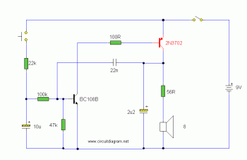
This is the schematic diagram of electronic siren circuit. The sound produced imitates the rise and fall of an American police siren. When very first switched on, the 10uF capacitors is discharged and each transistors are off. When the push button switch is pressed to 10uF capacitor will charge via the 22k resistor. This voltage is applied towards the base of the BC108B which will turn on slowly. When the switch is released the capacitor will discharge via the 100k and 47k base resistors and also the transistor will slowly turn off. The change in voltage alters the frequency of the electronic siren.

Electric current drain is fairly high in this electronic siren circuit so a appropriate power supply is needed. The duration the tone takes to rise and fall is determined by the 10uF and 22k resistor. These values may possibly be varied for various effects.

Simple LM358 Mic Preamplifier

Tags
Simple LM358 Mic Preamplifier


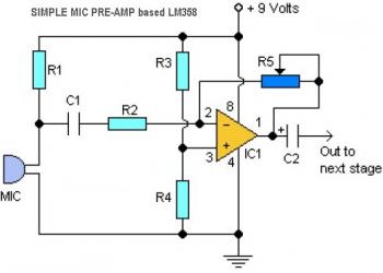
This is a simple LM358 microphone preamplifier schematic diagram. The pre-amp circuit is very easy to build and.. it's a low cost project... The variable resistor R5 is to adjust the LM358 op-amp gain. The LM358 has dual op-amp circuit modules, you may use a single LM358 to build two channels mic preamplifier.

Parts List:
R1, R3, R4 = 10K
R2 = 1K
R5 = 100K-1M Potensiometer
C1 = 0.1uF
C2 = 4.7uF/16V
IC1 = LM358 dual op-amp single power supply
Mic = Electret Microphone